Today I’ll set the record straight on tandem circuit breakers. I’ll explain what they are, when they can be used, and how a home inspector can figure all of this out. This is an updated version of an article I wrote for the ASHI Reporter back in 2011.
First, a quick definition. A tandem circuit breaker is a double circuit breaker that takes up the space of a single circuit breaker on a panelboard. People also refer to them as duplex, slimline, twin, half-height, half-inch, double, and wafer breakers, depending on local customs. Oh, and cheater breakers too. While a two-pole circuit breaker gets connected to two different poles at a panelboard and has a common trip or a handle tie for simultaneous disconnecting of two poles, a tandem breaker does not.
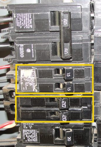
The photo below shows a 60-amp two-pole circuit breaker at the top, then a 15-amp tandem circuit breaker (highlighted), then a 20-amp tandem circuit breaker (highlighted), then a 20-amp single-pole circuit breaker at the bottom.
The next photo shows an older style tandem breaker found in Square D panelboards.
Because tandem circuit breakers allow for two circuits to be installed on a panelboard in a one circuit breaker space, they’re typically used after a panelboard has been filled to capacity with standard circuit breakers. Because of this, they’re often referred to as “cheaters.”
Despite the misnomer, this is not cheating. It’s perfectly fine to use tandem circuit breakers on any panelboard that’s designed for tandem circuit breakers, provided they’re installed in the proper locations.
How does a home inspector determine whether tandem circuit breakers are allowed on the panelboard they’re inspecting? There are a number of ways to do so.
Class CTL Panelboards
Panelboards must follow UL Standard 67, which requires all lighting and appliance panelboards to be Class CTL (Circuit Total Limiting). To help determine if tandem breakers are allowed, first consider the age of a panel.
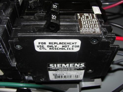
Pre-1965: Old panels that predate the CTL standard didn’t have a hard and fast rule for the number of circuit breakers allowed. Sometimes the panel has clear labeling, but usually is doesn’t on these old panels. In these cases, it’s possible that tandem circuit breakers are allowed in every space in the panel. These breakers will be labeled “For replacement use only. Not for CTL assemblies.”
1965 to 2008: Here’s an old formula for determining how many circuits are allowed in Class CTL panelboards made during this time period. This formula is helpful to use when you’re inspecting older electric panels without clear labeling inside the panel. Take the amperage of the panelboard, multiply by the number of poles, and divide by 10. It sounds complicated, but it’s not — let’s use a 100-amp panelboard as an example:
100 Amp x 2 Poles = 200
200 / 10 = 20
Based on this formula, the maximum number of circuits allowed in a 100-amp 120/240-volt panelboard is 20. A 150-amp panel would allow a maximum of 30 circuit poles, and a 200-amp panel would allow a maximum of 40 circuit poles. For panelboards not manufactured as “lighting & appliance” panelboards, there is no limit to the number of circuit breakers allowed. As a home inspector, this is helpful because if I look at a 100 amp panel with 20 spaces, I immediately know that the panel doesn’t allow tandem breakers. I don’t have to spend my time studying panel diagrams in this case.
2008 to today: For the newest panels, you simply go with what the manufacturer tells you, and the labeling is usually clear. Previous editions of the National Electric Code (NEC) limited the maximum number of circuits in a lighting and appliance panelboard to 42. The 2008 version of the NEC removed the “lighting & appliance” panelboard designation, however, NEC 408.54 says “A panelboard shall be provided with physical means to prevent the installation of more overcurrent devices than that number for which the panelboard was designed, rated, and listed.” Manufacturers still list the maximum number of circuit breakers allowed and must provide a rejection feature to help prevent the use of tandem circuit breakers where not allowed.
Rejection features
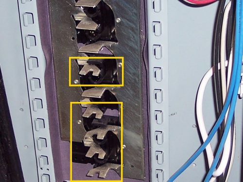
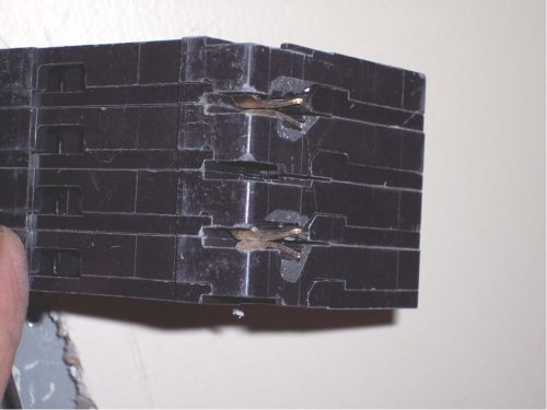
Class CTL panelboards have different methods of preventing class CTL tandem circuit breakers from being used in locations where they’re not allowed. This is referred to as a “rejection feature”. In the photo below, the highlighted bus stabs are notched to allow the use of tandem circuit breakers; the bus stabs which don’t have this notch won’t allow tandem breakers.
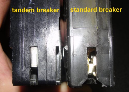
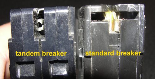
Class CTL tandem circuit breakers have a different shape than standard single-pole circuit breakers, to help prevent them from being installed where they don’t belong.
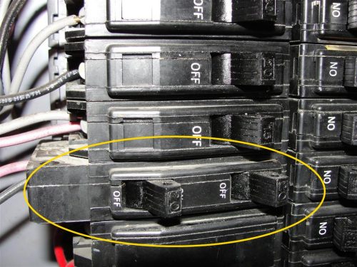
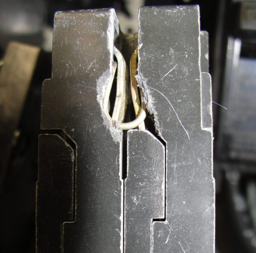
Tandem circuit breakers are manufactured this way in an effort to prevent people from using them in an improper manner, but this doesn’t stop everyone. In the photos below, you can see how someone broke the bottoms of the circuit breakers to make them fit where they didn’t belong. This is probably where the term “cheater” comes from.
As I mentioned above, panelboards manufactured before the adoption of the Class CTL standard allow non-Class CTL tandem circuit breakers to be installed. Non-Class CTL tandem circuit breakers do not have the ‘rejection’ feature that Class CTL breakers have. As clearly indicated by the label on the side of the circuit breaker pictured below, these circuit breakers are not allowed in ClassCTLpanelboards. The difficulty for us home inspectors is that we usually can’t see the marking after the breaker is installed. The only way to see this, usually, is to remove the breaker. And home inspectors shouldn’t be pulling circuit breakers during home inspections.
Does the panelboard allow tandems?
Now that I’ve talked about the general rules for tandem circuit breakers, I’ll discuss the ways that home inspectors or electrical inspectors can determine when tandem circuit breakers are allowed in various panelboards.
The model of the panelboard
The model or part number of the electric panelboard will usually indicate whether or not the electric panelboard is designed to accept tandem breakers and how many can be used. Here are a few examples:
- G3040BL1200 = 30 spaces, 40 total circuits allowed.
Up to 10 tandem circuit breakers can be used. - G3030BL1150 = 30 spaces, 30 total circuits allowed.
Tandem circuit breakers are not allowed. - BR1220B100 = 12 spaces, 20 total circuits allowed.
Up to 8 tandem circuit breakers can be used. - BR1212B100 = 12 spaces, 12 total circuits allowed.
Tandem circuit breakers are not allowed. - HOMC20U100C = 20 spaces, 20 total circuits allowed.
Tandem circuit breakers are not allowed.
I think it’s easy enough to see the pattern.
A diagram inside the panelboard
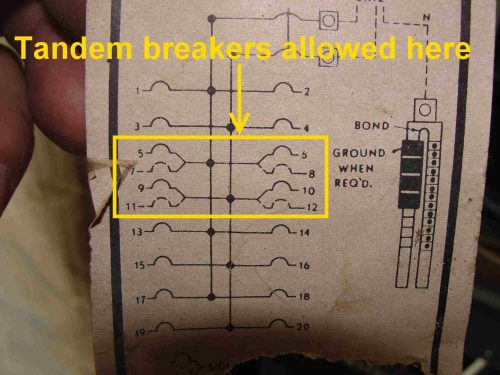
The wiring diagram inside the panelboard is a great way to determine if tandem breakers are allowed and, if so, exactly where they’re allowed. In the photo below, you can see that the top four spaces allow only full size breakers, while the bottom eight slots allow tandem breakers.
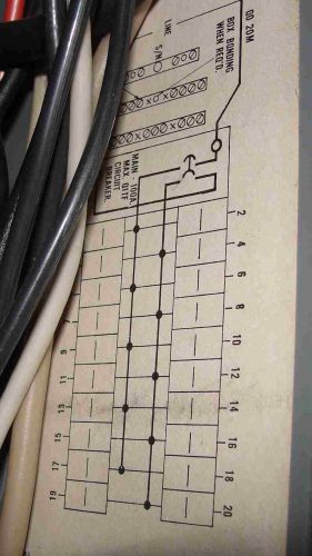
Here’s another panelboard diagram – this panelboard allows the use of tandem breakers in four locations.
And another – this panelboard doesn’t allow any tandem breakers.
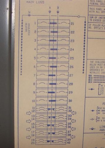
And another – this panelboard allows tandem breakers in the bottom ten spaces only (11-20 and 31-40).
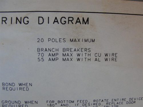
Another easy thing to look for is a label stating the maximum number of circuits allowed. In the photo below, you can see that only 20 circuits are allowed at the panelboard. This panelboard has 20 full-size spaces, so tandem circuit breakers aren’t allowed.
What’s the concern with tandem circuit breakers?
When tandem circuit breakers are used in locations where they’re not allowed, they could make an improper physical connection to the bus bar in the panelboard, which can create a fire hazard. Tandem circuit breakers also increase the total load on the bus bars in a panelboard; this is where home inspectors need to use common sense.
When a home inspector finds tandem circuit breakers used in improper locations, they’ll often recommend repair by an electrician. If the bus bars of the panelboard have been damaged or altered to allow for the installation of tandem circuit breakers, the proper repair is to have the panelboard replaced. There is no way for a home inspector to determine if the bus bars have been damaged without actually removing the circuit breakers, which is something home inspectors shouldn’t be doing.
Information for this article was provided, in part, by Alan Manche of Schneider Electric, Stephen Ploszay of Siemens Industry, Inc., and Joseph Fello of Eaton Corporation. Also, a special thanks to Retired ASHI Member Douglas Hansen.

